Dec 17


I am in the process of installing a Nexus 7 Tablet permanently in my Car – Using it for Navigation software and playing music.

I need to be able to tell the Nexus 7 to pause playback of music, and go to sleep. The easiest and most simple way is to touch a NFC tag to it, that tells it to do just this (Using a combination of NFC Task Launcher & Tasker)

But, how to enable the tag at will ?!

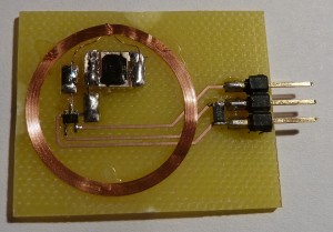
Solution: Put a CMOS switch in series with the antenna of the tag – this way it will only be readable when i tell it to!

A good solution is the 74HC4066 or even the DY411DY, but those are just too big an complicated. Why not resort to a single CMOS switch – Enter the 74LVC1G66.

A small SOT353 device that does it all, albeit a bit small for most soldering irons, but nothing my Weller WD1000M can’t handle.

I drew up a board in Eagle cad and milled a PCB. It didn’t work in the first try, it seems I damaged the RFID chip when removing it from the blob of glue inside the tag, so next chip i mounted sits on a big glob of glue, no need to risk damaging another chip!

I the second try, it works perfectly! – The chip needs a supply voltage of 3,3 or 5V and a logic high signal to trigger the Tag “ON”


Here is a Video of it in action!:


Attached is the Eagle files for your perusal.


EAGLE FILES: RFID_brd

 

Feb 12

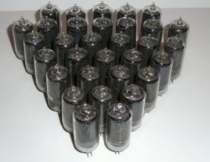
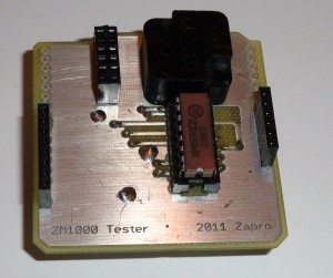
Recently, i purchased a big lot of Philips ZM1000 Nixies, and needed a test PCB to test out if all was good – i got sockets for a number of the tubes, so i settled on making a PCB with the correct socket, so I easily can test them.

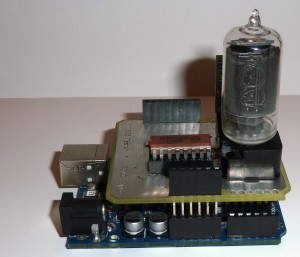
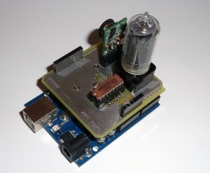
Being fond of the Arduino, i just thought, why not make it an Arduino shield – this way it’s a nice compact solution, powered by the USB-port, and no extra cables needed.

I earlier on aquired one of the real nice high voltage supplies, perfect for nixies from Taylor Electronics

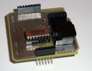
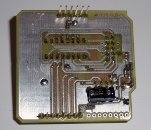
So i made a single PCB that fits the small power supply module, a socket for a 74141 Nixie driver, and a socket for the ZM1000 tube.

I milled the PCB on our PCB milling machine in the local hackerspace where i frequent, Labitat

I did not mount all the headers on the finished PCB, since they are not in used. The use of stacking headers are a little waste, since there is no way I can mount anything on top of the Nixie PCB, but they make the PCB headers more mechanically stable, since they are soldered on on the bottom side of the PCB.

A small video of the circuit in operation, running a simple counting program, testing all digits: Youtube


Video:

You can get the Eagle PCB files for the project here: ZM1000_Shield

Jan 24

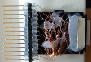
Wow, i didn’t expect being featured on Hacked Gadgets with my *ugly* LCD ribbon connector hack, but what the hell.


Thank you guys!

// Per.

Jul 17

Programming Arduino Mini’s and similar units with no on-board USB requires a USB/RS232 adaptor for the computer (unless you really have a RS232 port on your PC, then you need a MAX232 Level Translator)

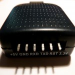
I scoured eBay to find the cheapest converter, and i found this.

Looking a bit further, for a bit more you can get this that is housed in a nice case [link]

These units use the CP2102 USB to TTL converter chip [Datasheet]

Funnily enough, the RST pin is brought out, this pin, when taken low will make the CP2102 go into low power mode and de-enumerate. You can wake up a computer in sleep mode by toggling this pin.

But i do not need to do this, i’m more interested in using this for programming Arduino’s.

Arduino’s use the DTR pin for the reset of the bootloader, and this pin is fortunately at the very corner of the QFN chip so it’s easy to get to.

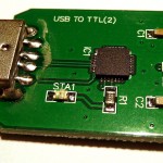
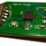
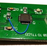
Removing the pullup resistor [R2] and soldering a small wire from the DTR pin to the RST pin brings out the DTR pin for Arduino programming.

I cut the original trace for the RST pin on the underside of the PCB, but i was too lazy to take a picture of that.

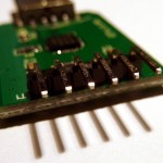
When i was modifying the unit i replaced the header pins too, since they looked like they were soldered on the wrong way round, they don’t really fit in the cutout of the case…

Some pics of the modification:


Jun 22

Hi folks. A fellow member in Labitat, Peter assembles electronics for Makerbot, at the moment he is making:

  • Makerbot Motherboard v2.4
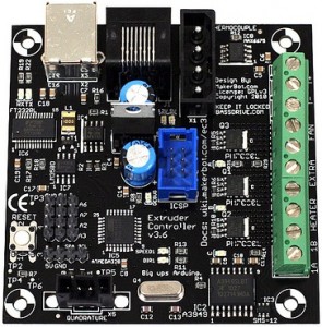
  • Extruder Controller v3.6
  • Stepper motor driver v3.3
  • Mech endstop v1.2


I bought a set of electronics for my RepRap Mendel that is in the making at the moment.

Peter was foresighted and fitted an Atmega328p instead of the bog standard Atmega168 that is a bit old today, this way the EC will have room for improvements which is not bad!

The standard ReplicatorG software cannot program the Atmega328p at this moment, but you can modify it by compiling the code your self, and add something in the firmware.xml – but i don’t see this as a good solution, since you won’t get updated firmware from Makerbot this way.

If you want to program your Extruder Controller fitted with a Atmea328p, follow this guide and it will work out for you:

http://wiki.makerbot.com/v2-firmware

A beginner’s mistake was writing

scons -f SConstruct.extruder
scons -f SConstruct.extruder port=/dev/SERIALDEVICE upload
It didn't work because i had not read all the instructions. It defaults to compiling
the code for the old Extruder Board 2.2 and not the Extruder Board v3.4
So running this made it work:
scons -f SConstruct.extruder platform=ecv34
scons -f SConstruct.extruder flatform=ecv34 port=/dev/SERIALDEVICE upload
This compiles the code from source to your Atmega168-fitted boards. To compile for
the Atmega328p you need to do these changes:

inside the /G3Firmware/v2/src/Extruder/ there is a SConscript file, edit this.
if platform == 'ec36':
platform = 'ecv34'
default_baud = '19200'
mcu='atmega168'
Edit it so it says this:
if platform == 'ec36':
platform = 'ecv34'
default_baud = '57600'
mcu='atmega328p'

Further down the file change this:
elif (platform == 'ecv34'):
default_baud = '19200'
mcu='atmega168'
So it reads like this:
elif (platform == 'ecv34'):
default_baud = '57600'
mcu='atmega328p'
With these changes you can compile for the Atmega328 ;-)


Jun 10

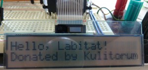
A member of Labitat, [Kulitorum] donated around 50 telephones to labitat since his work place scrapped them.

I took one of the phones home to reverse engineer the LCD. After about 10 minutes with the logic analyser, it was clear that it’s based on the Hitachi HD44780 or compatible controller.

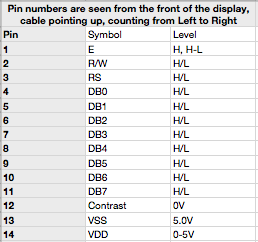
Just connect the contrast pin to GND, then contrast is perfect for most projects – unfortunately the LCD is meant to be viewed from an angle, and is not good for a front panel etc. that you will view front-on.

I drew up the connections here:


Some pctures of the LCD and the adaptor i soldered up.


The phones contain some other nice parts, a DC-DC converter module some Xtal’s, Electret microphone, speaker etc.


Jun 01

Was cleaning out in the shed today, and found an old piece of kit, some kind of controller box from Evans & Sutherland with 8 encoders and 8 pcs. 8-digit LED readout

The Display units are intelligent Alphanumeric LED readouts, have to do something with them some day… Anyway, the encoders is HP QEDS-7596, enclosed optical encoders, 512 pulses per revolution. Very nice encoders, must have cost a small fortune!

Wired it to my Arduino (yep, still playing with it, hehe) and opened a serial terminal to see the position of the encoder wheel, works nicely, the resolution of these encoders are just insane.

Googled around, i wanted to show the result on my computer (i’m using a Mac) and have read about processing, but never tried it. Now i had a reason to try it out.

Downloaded it, and got it running in a few minutes, it’s just as plug and play as the arduino, very nice!

I’ll upload some pictures of the result soon.


May 29

I have these displays from an old Ship navigator i scrapped for parts.

It was a Philips Navigator, model F 505-2

I kept the displays as the three PCF8576 controller chips sat nicely behind the display glass, so i cut the PCB along the smart mechanism that holds the display glass and elastomers tight to the PCB 🙂

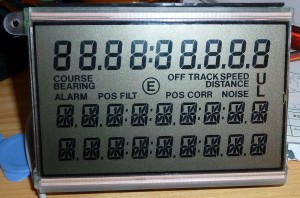
It’s a quite curious design, the first 9 digits are standard 7-segment letters, and a bunch of symbols.

The last 18 digits are 11-segments, nor 12, 14 or 16 which seems to be the “standard” around…

Each of the last 18 characters needs 12 data bits, so writing them becomes quite a challenge, as one can only send 8 bits at a time with the I2C-bus. So writing the first character is 8 bits and you can control 8 segments, and the next byte, the first nibble is the remaining segments for the first digit etc.

So addressing the display is like this

  1. DIGIT1(8 Bits)
  2. DIGIT1(4 Bits)/DIGIT2 (4 Bits)
  3. DIGIT2(8 Bits)
  4. Etc….

Before scrapping the navigator completely, i hooked up my logic analyser to see how the chips were adressed via the I2C-bus.

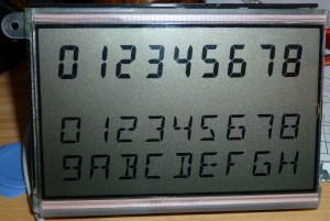
A shot with all segments lit:

I wrote a simple and _ugly_ program for the Arduino to test the display, and the results can be seen here:

You can get the Arduino-program here.

May 22

Waiting for my RepRap to be finished i could just as well get to know the Arduino hardware, so i installed the programming environment from Arduino on my Mac. That went real easy and it worked in the first try. Success!

What do you start out on with a new board/compiler ? Blink an LED of course! Looking in the /File/Examples/Basics/Blink there was a test program to blink the LED on the Arduino board. Worked just fine 🙂

Next i needed to try something a bit more exciting, so i dug up my trusty ‘ol PLED display (Organic LED) with a KS0066 controller (it’s HD44780 Compatible) and tried to get it work – no go, it simply wouldn’t work, so maybe it got damaged during moving my stuff – who knows.

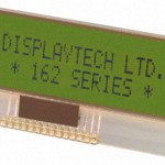
I whipped up some wires and a bit more standard LCD display, the 162COG-BA-BC and it worked fine.

But what is fun using a standard LCD – that has to be the oldest hack in the shed – apart from the Blinking LED example.

I knew i had some NOS VFD displays kicking around somewhere, that i got from a former employer. They was controlled by SPI bus and were 1×16 character standard ASCII.

I dug them up from my Display box (yep, i actually have two boxes ONLY with displays and display-related technology, among Nixie tubes etc.)

Tried getting them to work by adjusting the example suppled with the arduino found in /File/Examples/SPI/DigitalPotControl

It simply wouldn’t work reliably, i got i to show some very dim characters and it gave me a audible whine when i changed the display contents, but almost nothing was showing on the display.

Then i caught the smell of fish! – it turns out that two capacitors on these NOS displays was leaking Electrolyte all over the PCB and main switcher, i just hadn’t seen it. Incredible for NOS electronics that has never been used (i hooked these up for a short moment when i got them years ago, but otherwise unused)

Capacitors C4 (10μF/50V) and C9 (100μF/10V) seemed to be bad – especially the C4 (SMD) it was leaking all over the switcher. I replaced both and the display sprang to life immediately.

A datasheet for the display can be found here: CU165ECPB-T2J and here: CU165ECPB_T2J_specification

You can get my test routine here – it’s very ugly but it works.

UPDATE: After looking a bit around on the net, i actually found someone else that has been playing with the same display, just on a PCB from HP. You can find documentation and a library here

May 21

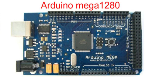
Today the postman came with my Arduino Mega 1280, i ordered it on eBay link.

It’s actually destined for my RepRap that i am amidst of building right now – i have it all done, but need to make the X carriage, extruder and then i need the Motherboard, stepper controllers etc.

A fellow member at Labitat is supplying me with the boards i need 🙂