Aug 10

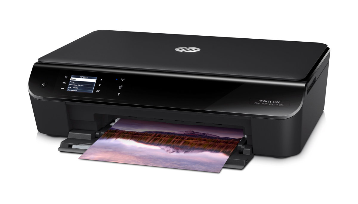
The usual trashpicking yielded a nice HP Envy 4500 AIO with missing top cover on the flatbed scanner.

Before just ripping it to pieces, i wondered how good the WiFi-support/setup was regarding the scanner, so i got it going. It complained about empty cartridges (no surprise here) but eventually i got to setup menu, enabled WPS and got it connected to my home WiFi.

My Mac immediately found it and installed it via Bonjour/AirPrint – no drivers needed (or i already had it on the system)

Scanning seemed to work just fine, so now i was wondering. Could the printer mechanism be discarded and the printer turned into a WiFi-enabled scanner?

First try: Disconnect FFC to the print carriage, boot printer and see what happens. Well, it was not happy. I got an error message in a rather crude font, so it died pretty much early in the boot process, before the “GUI” was up.

So apparently, it needs to talk to the de-serialiser/buffer chip on the carriage. I plugged the cable back in, removed the cartridges and tried again. This time it booted all the way and got onto WiFi. Scanner was still fully usable – Yay!

Next cause of action was to remove that stupid “lid open”-sensor. It’s just an opto-fork on the back side of the control/LCD/panel. Desoldering it from the board will keep it happy (there is a pullup on the receiving phototransistor inside it, so with the component missing, it looks like it’s in darkness – e.g. the lid is closed on the printer).

So, how much else can be unplugged you ask? Well, pretty much everything!

I unplugged cables for “cleaning station”, paper encoder, the two DC-motors and it still booted up – i got a shitload of error messages when doing this, but WiFi still works.

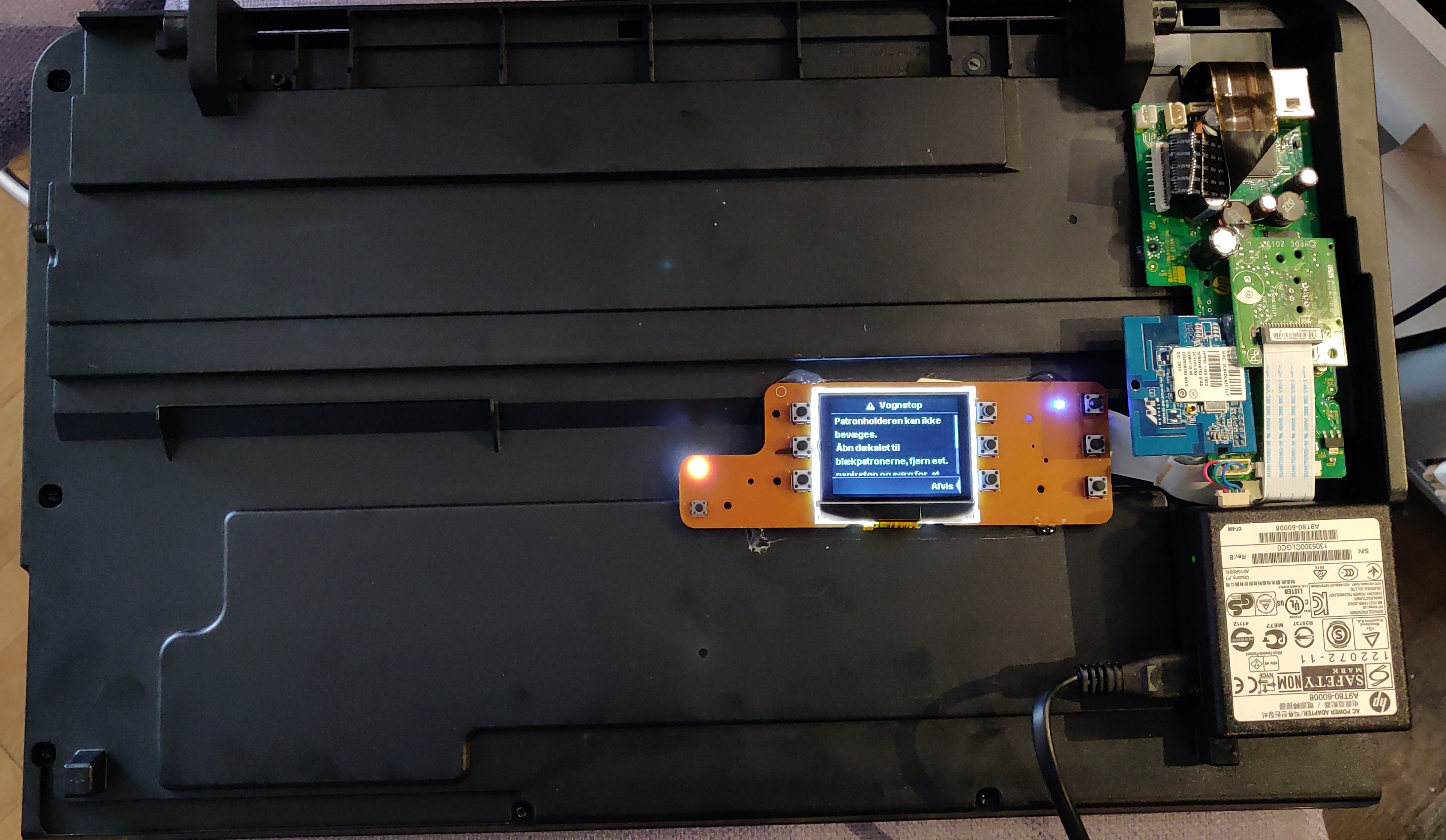
Now i’m pretty long in the modification process, and i come to think of – how do i set this up for a new WiFi-network some other day? – Pressing the buttons on the LCD control panel is of no help. Error messages keep popping up faster than i can navigate the menu – F*ck!

Plugging in back all the stuff yielded me with “No cartridges found” instead of the dreaded “Carriage is stuck” – but still no way to access the menu. At this point i had taken apart the carriage and removed all the mechanics and only kept the PCB with flex cables – so no plugging in back the cartridges!

Then i came to wonder – can you setup WiFi from the software/driver on the computer? – Oh yes you can – Even if your printer is completely bonkers and is reporting more errors than you can count to!

So connecting the printer via USB, and messing around in drivers control panel, calling up the Toolbox, i was able to scan for WiFi-networks, and connect to one. Success!

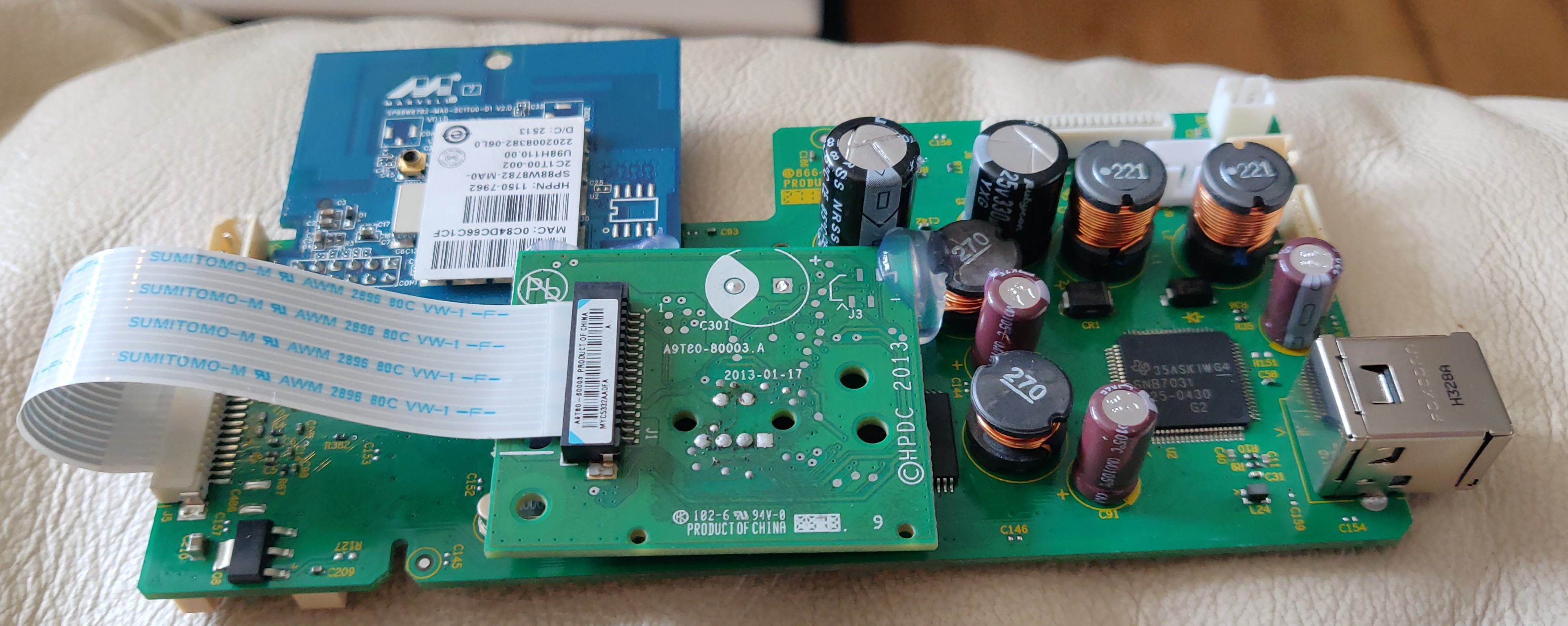
So now i have the machine pretty much sorted out. All the printer mechanism is gone, only the small PCB with the De-serialiser/Buffer is needed. I ripped off the flex cable to the cartridges, desoldered the electrolytic cap and the encoder for the optical strip.

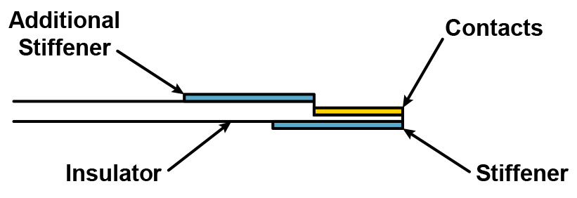
The original FFC from carriage to main board was rather long, so i went into my box of assorted ones to hunt for a shorter replacement. Shortly after i found out the cable i needed was a “flipped” cable – the connections on each end of the FFC is on each side of the cable. I couldn’t find a short cable that was flipped.

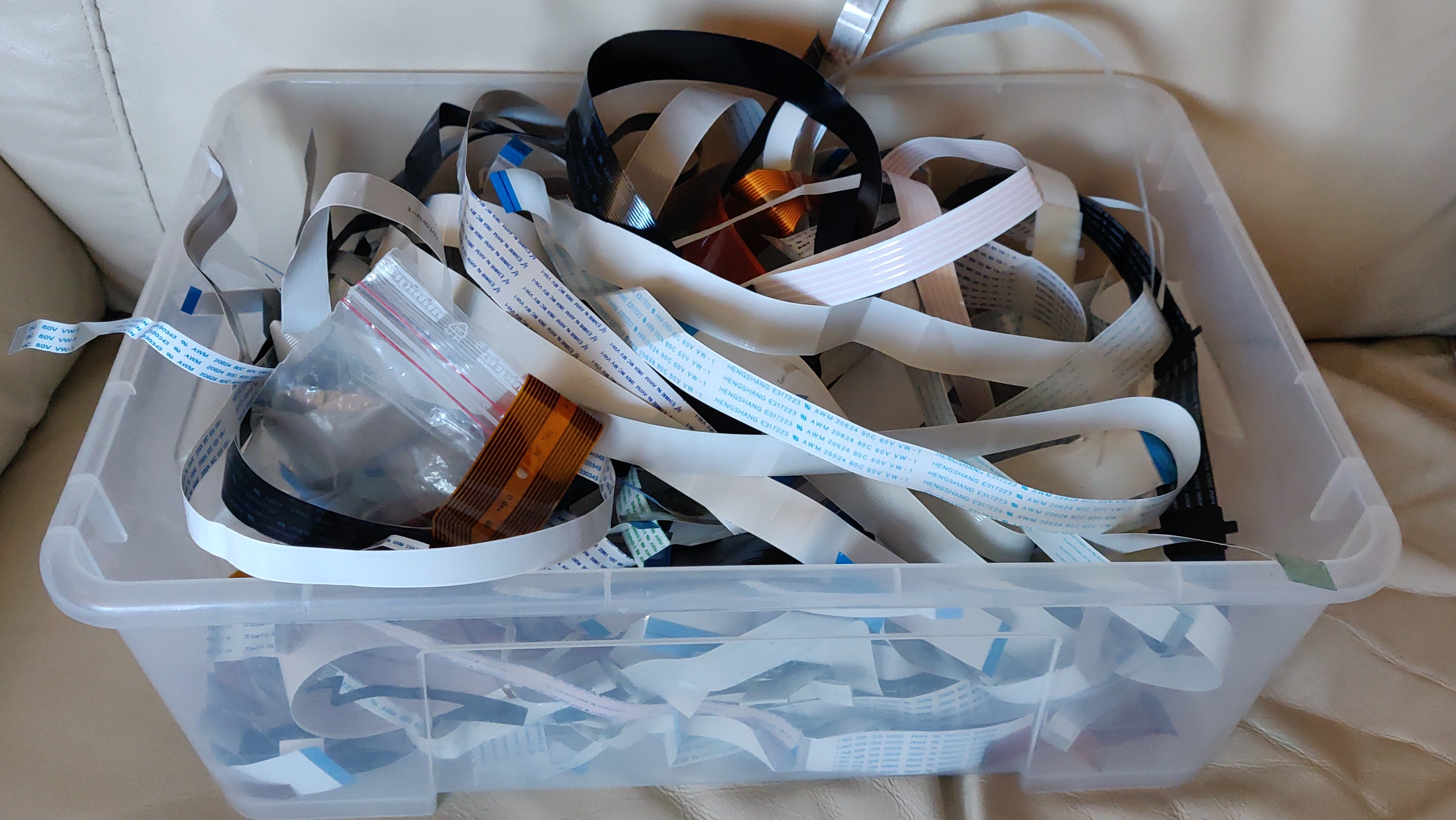
I found a reasonable short cable, ripped off the stiffener at the end, cut the cable clean off, and scratched the “back side” of the cable with a knife until the tracks appeared. The stiffener was glued back onto the other side of the cable, and then i had a short, flipped FFC.

The boards was arranged and put on top of each other with some hot glue.


The resulting parts were again hot-glued to the bottom of the scanner case.


Final touch would be some 3D-printed feet so it can sit flat on a table. Right now it’s a bit uneven on the bottom because of the power supply in the front right corner.

I hope this inspired you to do some hacking on your own – Personally i really had no need for an WiFi-enabled scanner. I already have a fine scanner with ADF and all the bells and whistles, but this afternoon project was more like I’ll hack it just because i can!

Nov 23

EDIT: Read bottom of post!

I have been toying around with GSM modems for some time – working on the Rotary Cellphone project, i settled on the SIM900-module from SIMCOM.

Milled SIM900-board

Early in my quest, i mistakenly read, that the SIM900 was Quad band, and the SIM900A was Dual band. As I decided that i did not need the Quad-band capability, i ordered the SIM900A-modem, as it was a few $ cheaper.

Ordering the first module from far east (AliExpress) my choice was the SIM900A model. I milled a breakout-board for the GSM-module, soldered it on, and everything “seemed” to work, but i could not register the modem on the Danish GSM-network. It acted like it was locked to a specific GSM-vendor.

The modem being brand new, ruled out the option that someone else had a go at it, so what was happening ?

I trawled the documentation at SIMCOM, and couldn’t readily find any information on what the differences between a SIM900 and a SIM900A-model were.

Some helpful people at the local Hackerspace mailing-list soon found the culprit (i guess their Google-fu was better than mine)

The SIM900A-model is locked to these regions:

  • China
  • India
  • Singapore
  • Malaysia
  • Thailand
  • Indonesia
  • Cambodia
  • Vietnam
  • Laos
  • Burma
  • Brunei
  • Philippines
  • East Timor

Official documentation is mirrored here: SIM900A Supported MCC List V1.00

Why SIMCOM makes this module, locked to specific regions, i do not know, if you have any idea why, please leave a comment.

User [] had luck upgrading the Firmware on his module – you can read about his findings here – i have not tested the firmware file, as i destroyed my 900A-model in frustration and anger.

Feb 08

First initial testing, after fixing some minor errors i made in the layout (Swapped RX/TX, not first time) and swapped D & S on the Fets. Grrr…

Feb 04

I’m in the process of building a 5x5x5 LED Cube like many others. The firmware is designed by [SiGNOUT] and [knielsen] from the local Hackerspace.

Their Cubes use a Seperate Arduino, and TLC5940 LED-drivers in TSOP housing. I would like to push the limits on my version of it, so i ordered the TLC5940 and Atmega328P in the smallest possible cases available. I would like to try BGA some day, but BGA requires more than dual layer PCB, so that’s impossible without professional PCB’s. The Atmel is 4mm² and the TLC5940 is 5mm².

The board is 2-layer and has holes through plated chemically. It is made on our Protomat & Minicontac II.

Here’s some pictures of the milled PCB:

Some more pictures in the Gallery

There’s pictures of another PCB in the folder, an Infrared LED exposure device for Playing with a Laser printer.

Jan 24

Wow, i didn’t expect being featured on Hacked Gadgets with my *ugly* LCD ribbon connector hack, but what the hell.


Thank you guys!

// Per.

Jul 17

Programming Arduino Mini’s and similar units with no on-board USB requires a USB/RS232 adaptor for the computer (unless you really have a RS232 port on your PC, then you need a MAX232 Level Translator)

I scoured eBay to find the cheapest converter, and i found this.

Looking a bit further, for a bit more you can get this that is housed in a nice case [link]

These units use the CP2102 USB to TTL converter chip [Datasheet]

Funnily enough, the RST pin is brought out, this pin, when taken low will make the CP2102 go into low power mode and de-enumerate. You can wake up a computer in sleep mode by toggling this pin.

But i do not need to do this, i’m more interested in using this for programming Arduino’s.

Arduino’s use the DTR pin for the reset of the bootloader, and this pin is fortunately at the very corner of the QFN chip so it’s easy to get to.

Removing the pullup resistor [R2] and soldering a small wire from the DTR pin to the RST pin brings out the DTR pin for Arduino programming.

I cut the original trace for the RST pin on the underside of the PCB, but i was too lazy to take a picture of that.

When i was modifying the unit i replaced the header pins too, since they looked like they were soldered on the wrong way round, they don’t really fit in the cutout of the case…

Some pics of the modification:


Jun 22

Hi folks. A fellow member in Labitat, Peter assembles electronics for Makerbot, at the moment he is making:

  • Makerbot Motherboard v2.4
  • Extruder Controller v3.6
  • Stepper motor driver v3.3
  • Mech endstop v1.2


I bought a set of electronics for my RepRap Mendel that is in the making at the moment.

Peter was foresighted and fitted an Atmega328p instead of the bog standard Atmega168 that is a bit old today, this way the EC will have room for improvements which is not bad!

The standard ReplicatorG software cannot program the Atmega328p at this moment, but you can modify it by compiling the code your self, and add something in the firmware.xml – but i don’t see this as a good solution, since you won’t get updated firmware from Makerbot this way.

If you want to program your Extruder Controller fitted with a Atmea328p, follow this guide and it will work out for you:

http://wiki.makerbot.com/v2-firmware

A beginner’s mistake was writing

scons -f SConstruct.extruder
scons -f SConstruct.extruder port=/dev/SERIALDEVICE upload
It didn't work because i had not read all the instructions. It defaults to compiling
the code for the old Extruder Board 2.2 and not the Extruder Board v3.4
So running this made it work:
scons -f SConstruct.extruder platform=ecv34
scons -f SConstruct.extruder flatform=ecv34 port=/dev/SERIALDEVICE upload
This compiles the code from source to your Atmega168-fitted boards. To compile for
the Atmega328p you need to do these changes:

inside the /G3Firmware/v2/src/Extruder/ there is a SConscript file, edit this.
if platform == 'ec36':
platform = 'ecv34'
default_baud = '19200'
mcu='atmega168'
Edit it so it says this:
if platform == 'ec36':
platform = 'ecv34'
default_baud = '57600'
mcu='atmega328p'

Further down the file change this:
elif (platform == 'ecv34'):
default_baud = '19200'
mcu='atmega168'
So it reads like this:
elif (platform == 'ecv34'):
default_baud = '57600'
mcu='atmega328p'
With these changes you can compile for the Atmega328 ;-)