Jun 01

Was cleaning out in the shed today, and found an old piece of kit, some kind of controller box from Evans & Sutherland with 8 encoders and 8 pcs. 8-digit LED readout

The Display units are intelligent Alphanumeric LED readouts, have to do something with them some day… Anyway, the encoders is HP QEDS-7596, enclosed optical encoders, 512 pulses per revolution. Very nice encoders, must have cost a small fortune!

Wired it to my Arduino (yep, still playing with it, hehe) and opened a serial terminal to see the position of the encoder wheel, works nicely, the resolution of these encoders are just insane.

Googled around, i wanted to show the result on my computer (i’m using a Mac) and have read about processing, but never tried it. Now i had a reason to try it out.

Downloaded it, and got it running in a few minutes, it’s just as plug and play as the arduino, very nice!

I’ll upload some pictures of the result soon.


May 29

I have these displays from an old Ship navigator i scrapped for parts.

It was a Philips Navigator, model F 505-2

I kept the displays as the three PCF8576 controller chips sat nicely behind the display glass, so i cut the PCB along the smart mechanism that holds the display glass and elastomers tight to the PCB 🙂

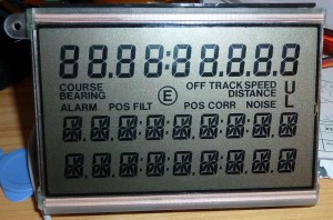
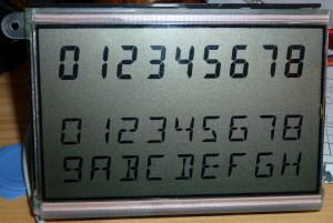
It’s a quite curious design, the first 9 digits are standard 7-segment letters, and a bunch of symbols.

The last 18 digits are 11-segments, nor 12, 14 or 16 which seems to be the “standard” around…

Each of the last 18 characters needs 12 data bits, so writing them becomes quite a challenge, as one can only send 8 bits at a time with the I2C-bus. So writing the first character is 8 bits and you can control 8 segments, and the next byte, the first nibble is the remaining segments for the first digit etc.

So addressing the display is like this

  1. DIGIT1(8 Bits)
  2. DIGIT1(4 Bits)/DIGIT2 (4 Bits)
  3. DIGIT2(8 Bits)
  4. Etc….

Before scrapping the navigator completely, i hooked up my logic analyser to see how the chips were adressed via the I2C-bus.

A shot with all segments lit:

I wrote a simple and _ugly_ program for the Arduino to test the display, and the results can be seen here:

You can get the Arduino-program here.

May 22

Waiting for my RepRap to be finished i could just as well get to know the Arduino hardware, so i installed the programming environment from Arduino on my Mac. That went real easy and it worked in the first try. Success!

What do you start out on with a new board/compiler ? Blink an LED of course! Looking in the /File/Examples/Basics/Blink there was a test program to blink the LED on the Arduino board. Worked just fine 🙂

Next i needed to try something a bit more exciting, so i dug up my trusty ‘ol PLED display (Organic LED) with a KS0066 controller (it’s HD44780 Compatible) and tried to get it work – no go, it simply wouldn’t work, so maybe it got damaged during moving my stuff – who knows.

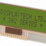
I whipped up some wires and a bit more standard LCD display, the 162COG-BA-BC and it worked fine.
But what is fun using a standard LCD – that has to be the oldest hack in the shed – apart from the Blinking LED example.

I knew i had some NOS VFD displays kicking around somewhere, that i got from a former employer. They was controlled by SPI bus and were 1×16 character standard ASCII.

I dug them up from my Display box (yep, i actually have two boxes ONLY with displays and display-related technology, among Nixie tubes etc.)

Tried getting them to work by adjusting the example suppled with the arduino found in /File/Examples/SPI/DigitalPotControl

It simply wouldn’t work reliably, i got i to show some very dim characters and it gave me a audible whine when i changed the display contents, but almost nothing was showing on the display.

Then i caught the smell of fish! – it turns out that two capacitors on these NOS displays was leaking Electrolyte all over the PCB and main switcher, i just hadn’t seen it. Incredible for NOS electronics that has never been used (i hooked these up for a short moment when i got them years ago, but otherwise unused)

Capacitors C4 (10μF/50V) and C9 (100μF/10V) seemed to be bad – especially the C4 (SMD) it was leaking all over the switcher. I replaced both and the display sprang to life immediately.

A datasheet for the display can be found here: CU165ECPB-T2J and here: CU165ECPB_T2J_specification

You can get my test routine here – it’s very ugly but it works.

UPDATE: After looking a bit around on the net, i actually found someone else that has been playing with the same display, just on a PCB from HP. You can find documentation and a library here
May 21

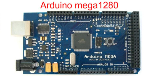
Today the postman came with my Arduino Mega 1280, i ordered it on eBay link.

It’s actually destined for my RepRap that i am amidst of building right now – i have it all done, but need to make the X carriage, extruder and then i need the Motherboard, stepper controllers etc.

A fellow member at Labitat is supplying me with the boards i need 🙂