
This is part 1 of my hacking adventures on the HT-A1. To see part 2, click here
After having tried to software-hack my old Flir E4 to get a higher resolution, and failed at that (some of them cannot be upgraded for unknown reasons), I was on the lookout for a better resolution device.
Having watched Julian Ilett’s video review of the device, steered me onto the cheap HTI (Dongguan Xintai Instrument Co.,Ltd.) HT-A1 thermal imager.
Almost all the other cheap off-brand imagers i have seen is pretty crap, but this one boasting a resolution of 220×160 pixels, that’s not half bad (compared to my old Flir E4, which was locked down at a measly 80×60 pixels.
Before pushing the Order button, i went to do some more research and found this teardown video by Youtube user “The Equalizor“.
This reveals that the camera uses a sensor module from SEEK thermal and reveals some other nice details. Go see his video on how to get into the device.
It looked good, so i ordered one using the link on Julian’s video. After approx 3 weeks (whereas one week was it being stuck in customs) it finally arrived. I turned it on and checked that all worked, and then to continue to take it apart 😀
This is not a review, nor a teardown. This has been done before. I will look into what’s happening on the serial interface that is clearly evident on the board, and i will try to figure out what kind of communication protocol there is between the sensor and the mainboard.
The mainboard in all its gory details. All pictures are clickable for magnification.
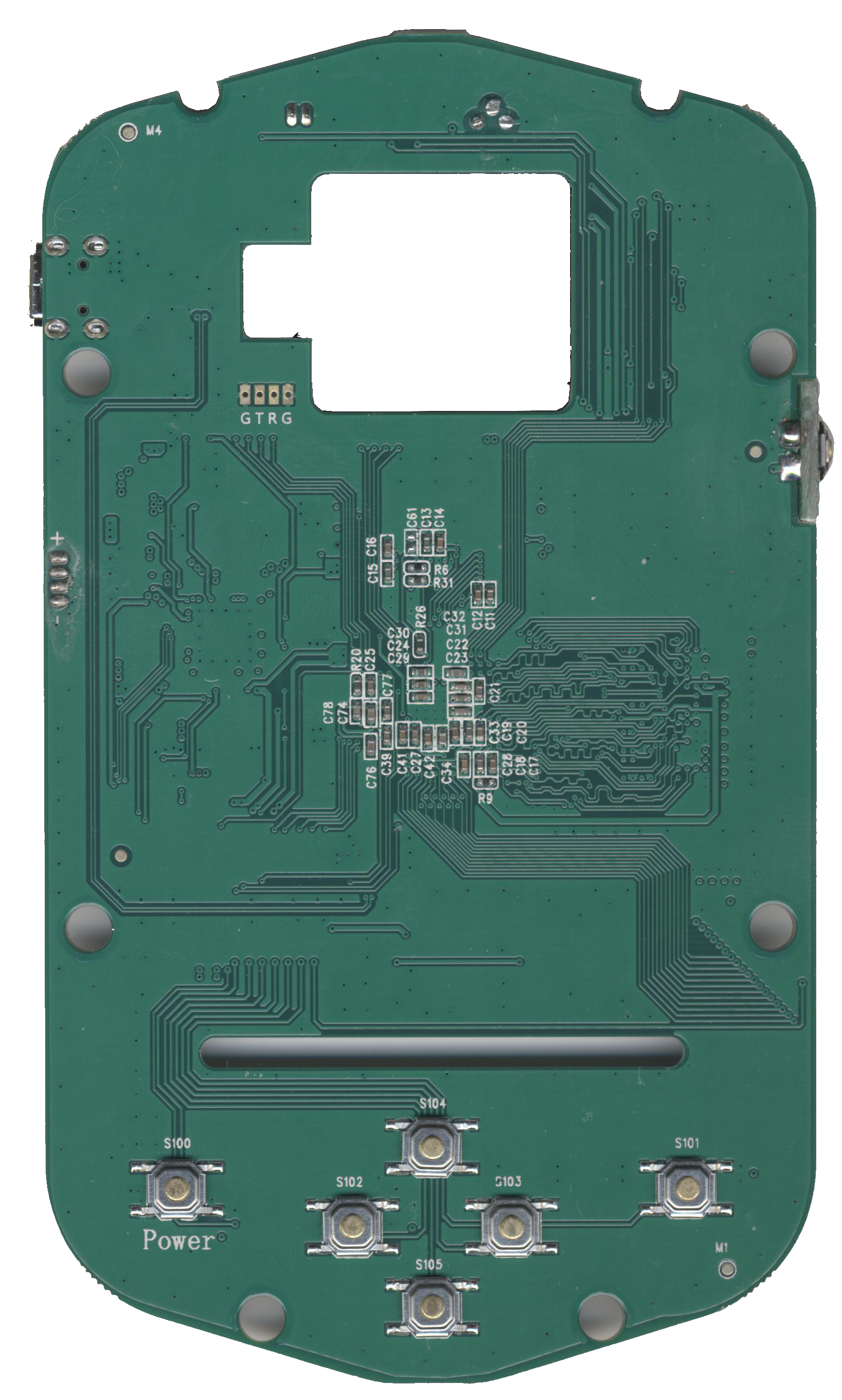
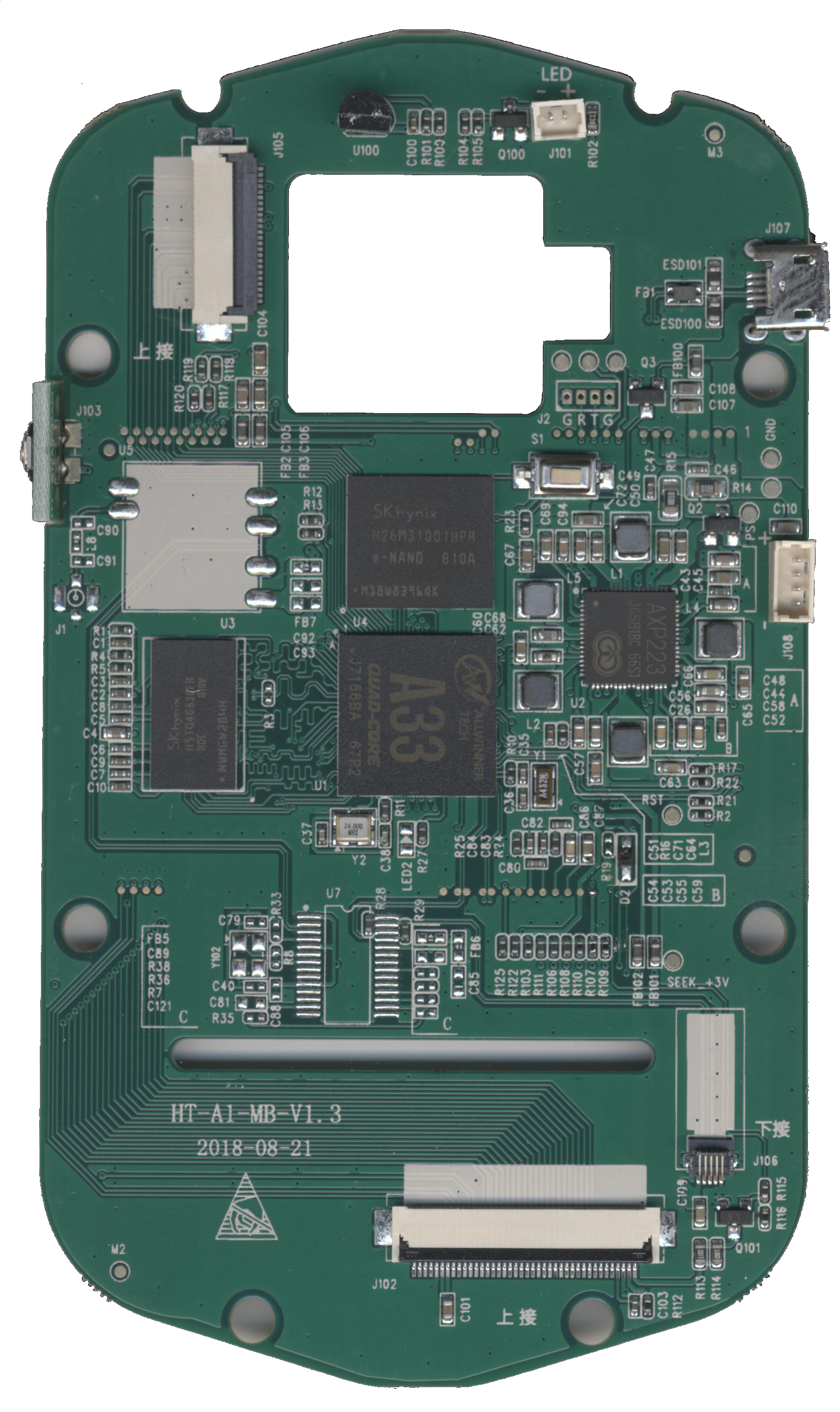
Apparently the mainboard is a quite new revision (August 21, 2018), and not carrying a CPU-daughter board like on The Equalizor‘s camera.
Looking at the mainboard, trying to figure out how everything is wired together, it becomes apparent that there is a room for a module of some kind, denoted U5. Hmm, GPS-module for geotagging or WiFi-module? The traces going off to J1 with the antenna matching components screams WiFi to me. Who makes a WiFi-module in this approx. 12x12mm footprint? EDIT: I found it, using the right search words on AliExpress: “Tablet WiFi module” – It’s a module carrying the RTL8188CUS WiFi-chip.
What is interesting, when we follow the tracks from this missing U5 module, they go to a missing U7 chip. The data pair from the thermal module also goes here, but is jumpered by two 0Ω resistors (R28 & R29) … Hmm this smells a lot like USB! – What is U7 was a missing USB-hub? I’m thinking GL850G in SSOP-28 housing, a good old classic. A datasheet is available here: GL850G USB Hub 1.07.
So, we know that the thermal imager is running USB communication with the main Allwinner A33 CPU. No need to put the logic analyzer on these lines for hacking – we need to look at that serial port to see what’s happening on boot!
The cable between the sensor and the mainboard, Front and back view.
It carries GND, +3.3V and USB data.
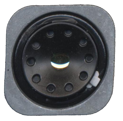
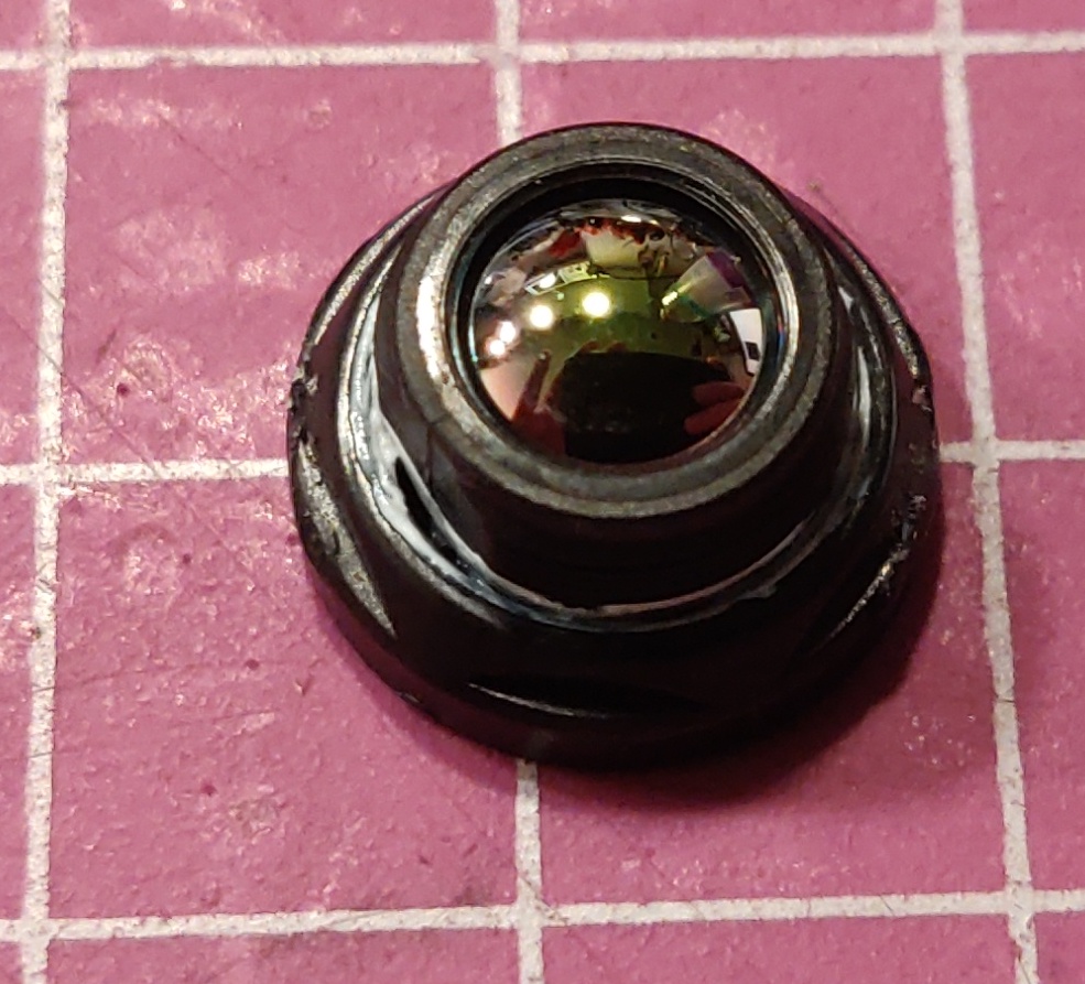
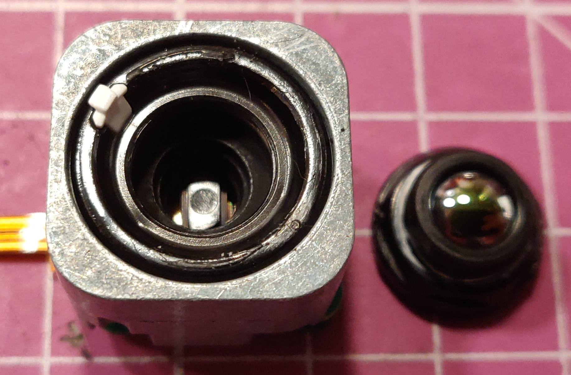
The sensor module itself:
Front of the sensor has a removable lens, held in place with two daubs of what seemed to be hot-melt adhesive. It was easily removed with a scalpel. I am planning to design and 3D-print a tool that fits into the holes in the front to be able to set the focus.
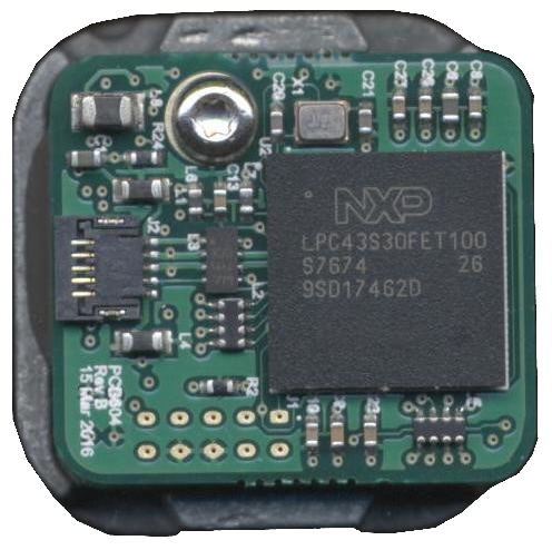
The processor on the thermal module is the NXP LPC4330FET100, a Dual-core Cortex M4/M0 chip. More info here
The camera module is a sandwich of two boards – front board holding the directly bonded sensor (this is pure speculations)
Bottom side of main PCB with the NXP micro holds some support circuitry and a big SPI flash that holds the firmware that runs the module.
On top of the main board, in vicinity of the thermal module there is U100, it’s a bog-standard DS18B20 thermometer for local compensation of the camera’s own temperature. I guess the thermal module does not carry its own temp. sensor.
Some playing around with booting the board without thermal imager or visible camera modules revealed that with both unplugged it will hang indefinitely at the boot screen (but it will still switch off when you press the power button, so it’s not dead behind the scenes). Unplugging only one of the cameras/sensors will have the camera booting happily. Unplugging the visible camera makes all mixed image modes go black. Unplugging the thermal module makes all thermal readings go away, but you can still use the visible module just fine. I guess it was built this way to not die completely if one of the devices went bad, but instead would boot and the user could see what was missing, to go report the error and get the device off for repair.
On the back of the board there is a switch, S1. I tried pressing it while the unit is in operation, no response.
Holding it down while pressing power button yields a device that does not boot, but rather “locks up” – I’m pretty sure this button is to go into some bootloader flash mode. The firmware talks about a “fel button” – it’s for firmware flashing as far as i know for now.
Well this is getting interesting!
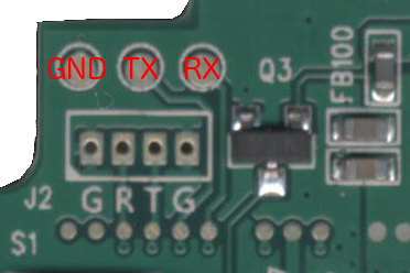
The small connector footprint J2 showed to contain no output at all, i scoped it and it’s dead as a dodo.
The three test pads over it on the other hand is alive and well with debug serial@115200 8N1 – YEAH!
Booting the camera with all devices connected will yield this nice bootlog:
HELLO! BOOT0 is starting!

boot0 version : 3.1.0

reg_addr 0x01f00100 =0x00000000

reg_addr 0x01f00104 =0x00000000

reg_addr 0x01f00108 =0x00000000

reg_addr 0x01f0010c =0x00000000

reg_addr 0x01f00110 =0x00000000

reg_addr 0x01f00114 =0x00000000

DRAM DRIVE INFO: V1.5

DRAM CLK =552 MHZ

DRAM simple test OK.

dram size =512

card boot number = 2

card no is 2

sdcard 2 line count 0

[mmc]: mmc driver ver 2014-07-07 16:54

[mmc]: ***Try SD card 2***

[mmc]: mmc 2 cmd 8 timeout, err 0x00000100

[mmc]: mmc 2 cmd 8 err 0x00000100

[mmc]: mmc 2 send if cond failed

[mmc]: mmc 2 cmd 55 timeout, err 0x00000100

[mmc]: mmc 2 cmd 55 err 0x00000100

[mmc]: mmc 2 send app cmd failed

[mmc]: ***Try MMC card 2***

[mmc]: MMC ver 4.5

[mmc]: SD/MMC Card: 4bit, capacity: 3728MB

[mmc]: vendor: Man 0x0090014a Snr 0x012084b9

[mmc]: product: H4G2a

[mmc]: revision: 1.1

[mmc]: ***SD/MMC 2 init OK!!!***

sdcard 2 init ok

The size of uboot is 0x000bc000.

sum=0x0ccccd69

src_sum=0x0ccccd69

set_mmc_para,sdly 50M 0

set_mmc_para,sdly 25M 0

Succeed in loading uboot from sdmmc flash.

Ready to disable icache.

Jump to secend Boot.

[      0.335]
The rest is not shown here, open BOOT down here under to see the full bootlog.
Raw logs from boot can be found here – some of them is booting without imagers connected, just to see how it reacts:
System is running Busybox, and with some serial debug magic i managed to copy files from system folders to the /mnt/IMGS folder that is exposed over USB. I found all kind of good stuff there – in /boot/ i found logos for other manufacturers (different branding), the cheesy battery recharge-animation – even audio files though the system has no way of doing audio recording or playback 😀


December 5th, 2018 at 22:52
Hi there Zapro,
just stumbled upon your hacks, nice work! I’ve seen The Equalizor’s video featured on Hackaday and ordered an A1 the same day; it arrived just yesterday. I’m probably not going to take mine apart too soon, because I have good use for it in working condition in the workshop. But there’s one question that immediately came to my mind when I read that the Thermal Module is connected via USB: Did you try to connect the module directly to a USB host like a Raspberry Pi or a PC? I’m wondering whether the Module spits out only raw data and all the other stuff (like color grading, spot readings, min-max readings) is done in the A33. Or is it all done in the Module itself?
Best regards from just behind the border to Germany! preamp.org
December 5th, 2018 at 23:00
Hi.
I didn’t try to plug it into a different host for a number of reasons.
1: We don’t have any driver for it, and without that, no use for it.
2: LSUSB on the device doesn’t look like it’s a generic UVC video source or similar.
3: It’s not not “video” from the sensor, also temperature etc -calibration is also done in the driver etc.
4: I might try to plug it into a desktop mashine at some point, but i’m 100% sure it will be pointless. No drivers = no fun.
I have dumped all the data partitions to .img files – i will post these soon on the blog for you to look into.
December 5th, 2018 at 23:21
Meh, damn drivers… I’d like to have an option to set a fixed temp scale, like 0°C…100°C instead of autorange. Maybe there’s a suitable option built-in already; looking forward to your .img-files.
December 6th, 2018 at 00:51
Driver ….the App from the Ht-101 ?
http://www.hti-meter.com/EN/html/product_view_278.html
https://www.alphaomega-electronics.com/es/index.php?controller=attachment&id_attachment=1552
December 6th, 2018 at 12:32
I looked into that. There is a “thermalviewer_hti” application in the Google appstore, but it crashes immediately on my phone (Oneplus 6 running Android 9.0)
Getting it to work on iPhone, forget about it. You need a special ID-chip in the game for the iPhone to acknowledge it.
December 7th, 2018 at 15:13
.img-files are up now 🙂
December 12th, 2018 at 20:05
Had a look at the .img-files. Seems like I have to up my linux-fu a notch…
Couldn’t resist any longer to take that thing apart though. The front glass came off pretty easy, even without using any extra heat. Now I’m trying to locate the serial port on my ”old” V1.1 board.
December 12th, 2018 at 21:30
Most of the .img-files are ext3-format, so you need to mount them as such.
Can you share some pics of your V1.1-board?
It could be interesting to compare differences in hardware and software.
December 12th, 2018 at 21:52
I used TestDisk to copy the files out of the images. Can’t make much sense of those .ELF-files though.
My board looks exactly like the one in the video. Just took a quick snap to show where I found the UART. Added a small three-pin header and then put the thing back together.
http://preamp.org/dinge/hta1_v1-1_uart.jpg
Do you care to share how you got access to the file system? I can look around the files via terminal, but how would I exchange things like the boot logo? Did you make the whole file system accessible via the USB port?
December 12th, 2018 at 22:01
I’m no linux geek either – i got help from a friend in the local hackerspace. We mounted the partitions read-only and then did a dd of them to /mnt/IMGS so the .img-files could be accessed over USB and pulled out.
You should use a serial terminal emulator that supports colors, otherwise it will be a bit hard to figure out what’s happening since the color commands are sent as extra characters. To edit the boot logo is quite simple:
1 from serial port, you have access to a local console on the camera. A ‘ls’ command will list files/folders.
Do a cd /boot/ to go to the boot folder. In here you will find bootlogo_20.bmp up to bootlogo_100.bmp.
Do a ‘cp bootlogo_20.bmp /mnt/IMGS/’ for all the files. Now they will be accessible over usb. Modify these, make sure they are in the same format as the old ones. Put them back on the USB share, then do a ‘cd /mnt/IMGS/’ and then ‘cp bootlogo_20.bmp /mnt/boot/’ etc.
December 12th, 2018 at 23:14
Hmm, easy enough. Didn’t think of that ;).
Works like a charm. In case you want to replace the battery charging bitmaps, you have to replace them in /boot/bat/ and also /boot/bat/80×166/ simultaneously. Change only one of them and there won’t be no charging animation anymore.
Here’s what my UART port looks like:
http://preamp.org/dinge/hta1_uart_access.jpg
Easy access for later ”updates” without having to open up that thing again. Not exactly weather proof anymore, but hey, something’s got to give…
December 12th, 2018 at 23:17
I tried replacing the battery charging symbols but i kept bricking it by doing that. So you say if you replace both places it works? That’s unusual …
I am waiting for my WiFi-module so i can enable permanent SSH-access 😀
December 12th, 2018 at 23:22
Yes, I’ve replaced them both and now it works like a charm! Wondered why there was no animation at all anymore when I just replaced a single file in a single folder. Replaced that same file in the other directory, too, and it worked again. Now I have replaced all the files (in both dirs) with my own version.
Good luck with that one! My board revision doesn’t have that option.
December 14th, 2018 at 13:52
Here’s what I’ve found out about the software so far.
The main program is called /work/app/ht-a1 and seems to contain everything compiled into that single file. The menu settings are stored in a file called /work/paras as simple hex values. The file is only 44 bytes long and I deciphered all the settings that you can choose with the menu and the arrow keys. While trying to find out what the other values do, I noticed that when some of them are set from 0x00 to 0x01 the software won’t load anymore. Deleting the paras file lets the software create a new one, so no problems here. Also it seems that some of the numerical values actually take up two or four bytes in the file, although a single byte would have been sufficient.
This is what I’ve got so far:
http://preamp.org/dinge/hta1_paras_file.png
I wasn’t able to locate the menu icons or the color maps inside of the software file yet, gonna have to dig a little deeper. I ran across the english menu texts though, and they seem to be easily changed, as long as the original length stays the same. I have successfully changed the text “Power off” to “Geht aus.” for example. Another interesting thing I found were translations for the menu in Italian and German, but I was not able to set them with the according byte in the paras file.
December 14th, 2018 at 14:11
Wow! – That’s so cool. I haven’t had the time (or interest) in digging in deeper yet, so amazing that you are doing that.
Can you confirm if you have the same software version on your camera as mine? Mine is 2.1.13 – if not, we could compare boot log and see if they changed something.
Geht aus!
// Per.
December 14th, 2018 at 19:47
Hehe, funny thing :). My software is 2.1.7, so a little older than yours. Turns out that I have found the German and Italian text in YOUR software – and in the menu there, too. I have now updated my software, thanks to your image files ;). And there’s actually another menu option to align the IR and VIS images on the screen, which was missing in my version altogether. Those settings are now saved in four additional bytes of the paras file, which makes it 48 bytes big.
Looks like there’s not much more to discover here. I was able to find some references for several ”icon_xyz.c” in the sources, but I have no clue what kind of files that may be. A search for popular image file headers (bmp, png, jpg, gif, ico) found nothing. There are some bytes that look like a black-to-white color palette (0x01 0x01 0x01 0x00 0x02 0x02 0x02 0x00 0x03 0x03 0x03 0x00 and so on) but I could not find the ‘Iron’ and ‘Spectrum’ counterparts, so I guess that’s not for the IR images.
Disassembly is not exactly my thing, but maybe it’s possible to utilize some of the other (driver?) files to make something from scratch…?
Why didn’t they just write that thing in python? Or at least leave the sources somewhere on the device xD!
December 14th, 2018 at 20:20
Not done yet!
I have changed that color palette a little, it made no visible difference anywhere. But it seems I have actually found the icons, more by accident than anything else though. Maybe I’ll change the spot markers to something a little more unobtrusive…? Photographic proof will follow if I’m successful.
December 14th, 2018 at 21:05
Cool!
Please do a detailed writeup on how to do this. I’m not enough of a software hacker to figure this out myself at the moment 😀
December 14th, 2018 at 21:16
Currently I’m trying to figure out in what file format those icons are stored. There’s some header information (including size of i.e. 24×24 pixels), a 4-bit palette for 16 colors and the raw pixel data, but it doesn’t fit bmp, pcx, ico, tga, … I even shifted that data around and fed every combination into ImageJ, but it didn’t like it.
I’m too lazy to whip up my own converter, although that should be pretty straightforward.
December 14th, 2018 at 23:49
Damn. The spot markers are drawn somewhere else, there’s only the spot marker icon from the menu. Not overly exciting, the menu doesn’t look too bad.
I’d like to remove some of the clutter from the main display area, like the center spot temp reading, which is also displayed in the upper left corner. Seems that’s all text and lines hidden in the binary somewhere though :(.
December 18th, 2018 at 21:37
Had a closer look at the color palettes in the output images to get a clue where to locate them in the software binary. Turns out that the slim palette bar graph displayed on the right edge is not a truthful representation of the colors used in the rest of the image! It’s not even full scale, especially around the hot end. The Black palette for example ranges from 0 to 255 in the actual image, while the bar graph only ranges from 8 to 223! That’s utter crap if you want to use an image manipulation program afterwards to determine the temperature of any given pixel – no problem with the grayscale palette, but impossible with the better looking spectra and iron palettes!
Guess that’s where the cheap price comes from o_0 … I remember having used a Fluke once, which included the complete temperature map inside the EXIF of the output JPEG image file.
December 18th, 2018 at 21:39
It would be awesome if the software could be modified to save two pictures at once – one in color and one in b/w – or save visual/thermal seperate like the Flir cameras do.
December 19th, 2018 at 22:07
Found the color palettes. They’re not part of the software itself, but of a library called “seekware”. There’re several versions in /lib folder, called seekware.so.2.6 for the newest version and four older versions (2.4, 2.5, 2.5.1, 2.5.2). There’s a symlink called seekware.so.2 which is linking to the latest file version. I have modified the 2.6 and added it as 2.6.1 to the bunch, updated the symlink (with ln -sf), rebooted, and now can have some unique color palettes.
http://preamp.org/dinge/hta1_lib.png
The seekware 2.6 contains a total of 29 palettes, where the two grayscales seem to be double each (1 and 29, 8 and 13). Number 28 is the ugly palette called “Cool”. I have replaced it with the palette data from Number 3 for a test. And it works :)!
http://preamp.org/dinge/hta1_seekware_palettes.png
Not sure why they only included 5 palettes and not all of them? Lazy to build a bigger selection menu? More features for a future, more expensive software? Licence issues? Who knows…
Here’s a sample image with the updated color palette. Note that the palette bar to the right still shows the original “Cool” palette. This must be another graphic embeddet into the main software, gonna have to dig for that, too…
http://preamp.org/dinge/hta1_new_palette.jpg
December 19th, 2018 at 23:19
You are either crazy or you have too much time 😀 It’s super awesome you’ve come this far. I didn’t have time to play with mine (and i’m not good enough with software anyway)
December 20th, 2018 at 11:38
With crazy people like this we can utilise the maximum out of our chinese measurement tools..
i don’t know why they don’t create a small website dedicated to their product and go more open with their software, it will be copied and hacked anyway and i rather but the original version to begin with
December 20th, 2018 at 14:18
Well for now they are violating the GPL, but writing them and asking for the source is fruitless. Chinese generally doesn’t care about GPL.
December 21st, 2018 at 09:28
I’m certainly a little crazy, but I’m mostly doing this for the fun of it ;).
You can call these guys crazy:
https://www.eevblog.com/forum/thermal-imaging/yet-another-cheap-thermal-imager-incoming/
Currently working through 2300+ posts, hoping to find some more info about that seek module.
December 30th, 2018 at 22:28
Not making much more progress now. I was able to shrink the battery symbol a little, as well as to reduce the “e=0.95” to a more brief “.95”.
http://preamp.org/dinge/hta1_pal_bat.jpg
That’s about it though. I could not find anything about the palette graphs, nor the spot markers; not even the temperature readings adjacent to them. I have modified the palette “Cool” (which looks really ugly) to something resembling a FLIR “Outdoor Alert” palette, which looks pretty badass, but that wrong-colored graph is a nuisance really :(. I’d be happy with disabling it altogether, but that’s probably needing some disassembly first. I tried objdump, but the offset values don’t line up with those from the hex editor. Close, but no cigar. I’m probably doing it wrong…
December 31st, 2018 at 15:48
Found a thing called RetDec… Wow!
On a first attempt I was able to NOP out each displayed element individually, so I now have a clear thermal image with only the battery indicator left. Next up I’ll try to figure out how to hide all that stuff with a key press, so that I can easily switch between a “thermal camera” and a “thermal imager” O:)
January 3rd, 2019 at 13:40
Success! Now, with a press of the UP button, I can hide the whole ‘HUD’ and get a clean image. Press it again, and all the spot markers and indicators are back. Wasn’t too hard after all, since the source contains debug information and thus a lot of labels for most of the functions. Had to recalculate some branch addresses though, which was rather tedious.
Next I’d love to get rid off the “save image” dialog and immediately save the image on button press. Not sure where to start there though; didn’t find any meaningful labels in that 7+MB disassembler output yet.
And, of course, fix that darn color palette bar. I’d be grateful for any hints. Here’s the output of the disassembler, including the original binary:
http://preamp.org/dinge/hta1_v13_retdec.7z
January 4th, 2019 at 13:43
Awesome. How do one apply this modification to a normal working HT-A1?
I would like to give it a go 🙂
January 4th, 2019 at 21:16
I’ll have to do a proper write-up one day… 🙂
Get a copy of your /work/app/ht-a1 file and open it up in your favourite hex editor. Find the following block of hex values:
70 B5 00 20 92 B0 FE F7 0F FF 06 46 00 20 FE F7 15 FF 05 46 68 46 FA F7 AF FC 01 9C 00 20 FE F7 79 FE 29 46 03 46 22 46 30 46 FE F7 C9 F9 01 20 FE F7 FA FE 05 46 01 20 FE F7 00 FF 04 46 01 20 FE F7 68 FE 21 46 02 46 28 46 FE F7 1B FD 02 20 FE F7 EA FE 05 46 02 20 FE F7 F0 FE 04 46 02 20 FE F7 58 FE 21 46 02 46 28 46 FE F7 3F FB FE F7 EF FE 05 20 FE F7 D8 FE 04 46 05 20 FE F7 DE FE 06 23 01 46 E0 22 20 46 FE F7 CE FB 03 20 FE F7 CB FE 05 46 03 20 FE F7 D1 FE 04 46 03 20 FE F7 39 FE 21 46 02 46 28 46 FE F7 00 FC 05 F0 80 FB 01 28 0E D0 05 F0 76 FB 01 28 01 D0 12 B0 70 BD 0A 20 82 21 4F F0 FF 32 12 B0 BD E8 70 40 FE F7 0D BD 06 20 FE F7 A8 FE 06 46 06 20 FE F7 AE FE 05 46 06 A8 FA F7 48 FC 09 9C 06 20 FE F7 12 FE 29 46 03 46 22 46 30 46 FE F7 E8 F9 07 20 FE F7 93 FE 06 46 07 20 FE F7 99 FE 05 46 0C A8 FA F7 33 FC 11 9C 07 20 FE F7 FD FD 29 46 03 46 22 46 30 46 FE F7 5B FA 08 20 FE F7 7E FE 05 46 08 20 FE F7 84 FE 04 46 08 20 FE F7 EC FD 21 46 02 46 28 46 FE F7 FD FA B5 E7
Since I’m actually using the software version you supplied with your image, that should be located at offset 0x7FB0 and the length be 0x148. Replace it with the following values:
70 B5 92 B0 05 F0 D4 FB 01 28 0E D0 05 F0 CA FB 01 28 01 D0 12 B0 70 BD 0A 20 82 21 4F F0 FF 32 12 B0 BD E8 70 40 FE F7 61 BD 00 20 FE F7 FC FE 06 46 00 20 FE F7 02 FF 05 46 68 46 FA F7 9C FC 01 9C 00 20 FE F7 66 FE 29 46 03 46 22 46 30 46 FE F7 B6 F9 01 20 FE F7 E7 FE 05 46 01 20 FE F7 ED FE 04 46 01 20 FE F7 55 FE 21 46 02 46 28 46 FE F7 08 FD 02 20 FE F7 D7 FE 05 46 02 20 FE F7 DD FE 04 46 02 20 FE F7 45 FE 21 46 02 46 28 46 FE F7 2C FB FE F7 DC FE 05 20 FE F7 C5 FE 04 46 05 20 FE F7 CB FE 06 23 01 46 E0 22 20 46 FE F7 BB FB 03 20 FE F7 B8 FE 05 46 03 20 FE F7 BE FE 04 46 03 20 FE F7 26 FE 21 46 02 46 28 46 FE F7 ED FB 06 20 FE F7 A8 FE 06 46 06 20 FE F7 AE FE 05 46 06 A8 FA F7 48 FC 09 9C 06 20 FE F7 12 FE 29 46 03 46 22 46 30 46 FE F7 E8 F9 07 20 FE F7 93 FE 06 46 07 20 FE F7 99 FE 05 46 0C A8 FA F7 33 FC 11 9C 07 20 FE F7 FD FD 29 46 03 46 22 46 30 46 FE F7 5B FA 08 20 FE F7 7E FE 05 46 08 20 FE F7 84 FE 04 46 08 20 FE F7 EC FD 21 46 02 46 28 46 FE F7 FD FA 61 E7
Then just copy the file over and reboot.
I’ve made a little video as proof, but since I’m not at YouTube, you’ll have to download the whole 74MB at once: http://preamp.org/dinge/hta1_hud-hack.mp4
January 8th, 2019 at 00:02
Finally found how the palette bar graph is rendered! There’s a function which draws the bar on the screen, as well as in the selection menu. Unfortunately, for each of the first three palettes (spectra, iron, cool) there’s only a set of five RGB values to create it, which makes it impossible to properly resemble a palette like Outdoor Alert :(. So I’ve opted to simply NOP that one out and thus don’t have a false-colored bar clutter up my images ;).
January 15th, 2019 at 22:29
Pulled off another hack. That wouldn’t have been possible without another great piece of software called Relyze, so give it a look ;).
I’m now able to reposition the individual HUD elements on the screen and resize the palette bar graph within 8bit limits (i.e. 256×256 pixel max). For a better legibility I moved the graph to the left side and put the max and min labels above and below it, respectively. And, of course, made the graph resemble the Tyrian palette, which I’ve put in there instead of the ‘Cool’ one. Here’s a picture:
http://preamp.org/dinge/hta1_hud_mod_tyrian_palette.jpg
I’m still thinking about replacing/updating that bland Arial font. Found out that it’s actually saved as a pixel font, each character in 6 different sizes, which makes this another tedious thing to tackle. I’d have to use a font with similar character width (like ‘i’ is smaller than ‘W’), so I’m not sure whether that’s worth the effort.
Oh, and here’s a final one :). That whole MsgBox-stuff gave me a minor headache, but I finally found out how to NOP it out and jump directly to the ‘Yes button pressed’ part. Now when you press the shutter, the image is saved immediately. The screen only freezes for half a second or so, then you can take the next picture. Very nice for photographing Firework rocket launches! Should be easy to implement for you. Find the following at offset 0xA4B8:
06 F0 8E FC 00 F0 3C FE 4D F2 90 00 C0 F2 03 00 F7 F7 CA EE 18 20 00 F0 47 FE FF E6
replace with:
06 F0 8E FC 00 BF 00 BF 4D F2 90 00 C0 F2 03 00 F7 F7 CA EE 06 F0 CA FD 18 20 FF E6
For the moment I’m pretty happy with my device now. Received a mail lately from the manufacturer though, who told me that the HT-A2 is out now. It has a full 320×200 thermal resolution, but is also much more expensive :(. From the screenshots on their web page the software looks pretty much the same, so it’s probably just using a better Seek Thermal module and skipping the upsampling.
What about your WiFi module? Any progress so far?
January 15th, 2019 at 22:37
Wow, i’m speechless.
Super awesome! – I didn’t get to play with your hex values last time you wrote since i was on christmas vacation. Now back, busy with working and repairs.
Just today all the parts for adding USB Hub + WiFi arrived, so if everything goes well, i will get to play with it at the end of the week!
I’m super excited.
I am planning to make another post part 2/2 with the modifications. I would like to share your findings as well – i’m thinking about how to recite your findings in a proper manner – you don’t have any plans for a small write-up that i could link to, maybe?
Regards.
January 15th, 2019 at 23:04
Nice!
I’m actually thinking about putting all that stuff up on my homepage, but I’m lazy doing writeups, so this may take a while. I’ll keep you posted once I get around to it, but in the meantime feel free to recite as much as you want or send me an email if you need some more infos.
Good luck on your mod! I’ll check back frequently ;).
May 6th, 2019 at 17:31
Ok so I opened my HT-18 too. Followed Preamp’s idea and built an acces port to it too:
https://www.dropbox.com/s/q8i1v5rma2kqynn/Photo%20May%2004%2C%2013%2017%2032.jpg?dl=0
https://www.dropbox.com/s/d8t4w2mdsw7xeur/Photo%20May%2004%2C%2013%2017%2037.jpg?dl=0
https://www.dropbox.com/s/qggn7gldjnm8si9/Photo%20May%2004%2C%2013%2015%2046.jpg?dl=0
https://www.dropbox.com/s/82bx6omfmg1pqmf/Photo%20May%2004%2C%2013%2015%2051.jpg?dl=0
I’ll also take a swing at those HEX values if they still match (running a newer FW) and update here.
Thank you Per and Pream for providing enough information, in order for me to build up the confidence and do it.
I am working on the files right now.
May 6th, 2019 at 19:48
Awesome, RamSet!
Unfortunately i’ve been so damn busy with other projects until now, but soon-ish i will get back to playing with mine, installing the WiFi-module etc.
May 6th, 2019 at 20:25
I did find some WiFi references, bluetooth probing and even HDMI output done (at some point) via software.
Unfortunately the file in my case, is different and the above addresses are not “there” and not even remotely close to the ones listed.
I would have wanted that whole clear screen thingy and the autosave … The easy part of the boot logos … yeah i did that first 🙂
May 7th, 2019 at 01:16
I was comparing the two images… of your board and mine. It looks like I have the U7 IC on the board.
I will open it again and take a better look at it. I will return with the information from it.
I ordered the WiFi module also and From what I’ve poked with the system, it will require modifications in the /boot/test_config.fex file as the WiFi probe commands points to the wrong path for the driver (in my case the driver is available further down a folder stored in /lib/modules/3.4.39/kernel/drivers.
One I’ll get the module, I’ll open it again to place it and then have a swing at it.
May 7th, 2019 at 12:14
Hi RamSet, send me your firmware file to preamp@web.de and I’ll see what I can do for you 🙂
May 7th, 2019 at 18:33
Preamp, Thank you so much !!!
I sent you an e-mail.
I tried to look at it myself and installed Relyze and also had a swing at RetDec (this one is saying No matching plugins found for ‘GCC 4.6.3’ and some other version ). Running an outdated Win7 with issues related to .dlls from the MS redistributable) and every attempt to run those programs fails.
Per, you were right, that chip is indeed a GL850G:
https://www.dropbox.com/s/52lwiwgsn66rn3v/Photo%20May%2007%2C%2008%2011%2038.jpg?dl=0
June 17th, 2019 at 19:02
Countless attempts into getting this working, I have finally reached a breaking point (for myself) and I’m giving up on it.
2 Different modules (RTL8188 -WiFi only and RTL8723BU – WiFI +Bluetooth) tested.
I couldn’t get them activated (driver related errors) and unfortunately I feel that I chased this for much longer than I wanted to.
Modules (installed) are seen and identified by the system but I can never get them to run/activate due to diver related errors. Compilation related errors, Parameters to be exact.
I got as far as this:
[ 3088.509931] RTL871X: module init start
[ 3088.509945] RTL871X: rtl8723bs v4.3.5_11487.20140519_BTCOEX20140507-4E40_beta
[ 3088.509955] RTL871X: build time: Sep 18 2017 02:25:50
[ 3088.509964] RTL871X: rtl8723bs BT-Coex version = BTCOEX20140507-4E40
[ 3088.509974] [wifi_pm]: wifi_used = 0, please check your config !!
[ 3088.509991] RTL871X: get wifi_sdc_id failed
[ 3088.509999] RTL871X: No definition of wake up host PIN
[ 3088.510117] RTL871X: rtw_drv_entry: power on failed!!(-1)
[ 3088.510142] RTL871X: module init ret=-1
calling it quits here …
June 21st, 2020 at 17:48
Hi, may I know what is the IR resolution of the sensor?
June 21st, 2020 at 18:40
Have you read the text of my post?
It says there in cleartext 🙂
September 10th, 2020 at 06:26
Does anyone have a video hack to get livestream from HT-19 thermal imager camera ?
September 10th, 2020 at 13:33
Without some heavy embedded linux hacking i don’t see any possibility of this happening, unfortunately.
May 1st, 2021 at 09:49
Hi Guys,
Anybody has any progress with hacking these HT-A1/A2 cameras?
I have a HT-A2 with firmware 2.1.8
It works well but i feel the color palettes are pretty bad and also when in color modes, the gain goes up a lot and images become fuzzy.
I only use the white hot as it looks to be the clearest.
It would be cool if someone could clean up on these and curious if any other improvements can be made.
I tried contacting the manufacturer but they never replied, not surprised there…
Thanks.